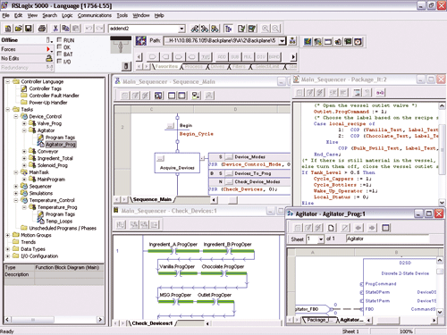
- Rockwell Rslogix 5000 User Manual
- Allen Bradley Rslogix 5000 User Manual Free
- Allen Bradley Rslogix 5000

Designed for both schools and individuals who wish to learn more than the basic trainers and instruction manuals can teach. NOTE: Lessons are currently being written for this trainer and you will find them in the Allen Bradley RsLogix 5000 PLC Trainer Lessons section when available. PLC Programming with RSLogix 5000. Learn PLC Programming with RSLogix 5000 for Allen-Bradley ControlLogix and CompactLogix PLCs. Filetype: Submitter: r9909 1756 - ControlLogix System User Manual - Scribd 1756 - ControlLogix System User Manual - Ebook download as PDF File (.pdf), Text file (.txt) or read book online. Nov 04, 2014 RSLogix 5000 Going online and uploading the program using a USB 1756-CP3 and Ethernet, see more help videos at www.PLCCable.com. Allen Bradley RSLogix 5000.
Requirements
- Allen-Bradley Edition or Ultimate Edition
- Compatible Logix5000 PLC with Ethernet connection
- RSLogix 5000
This tutorial gives you a step-by-step instructions on how to use a CompactLogix to control FACTORY I/O.Although this guide exemplifies with a CompactLogix, the same steps apply to a ControlLogix PLC.
Setting up communication between PC and PLC
Connect the PLC to the network.
Assign an IP address to the PLC.
To complete this step you should refer to the CompactLogix Controllers User Manual 1769-UM011, which describes methods to assign an IP address to the controller.
Start RSLinx and open the driver configuration dialog by selecting Communications > Configure Drivers from the menu.
Add an EtherNet/IP driver.
You should now be able to find the controller under the newly added driver.
Connecting FACTORY I/O to the PLC
In FACTORY I/O click on FILE > Driver Configuration to open the Driver Window.
Select Allen-Bradley Logix5000 from the driver drop-down list.
Open the driver Configuration Panel by clicking on CONFIGURATION.
Insert the controller's IP address into the Host field. On this panel, you can also define how many I/O Points to use, as well as the controller's tags they reference.
Each I/O point name (e.g. BOOL_IN_0) represents an existent PLC tag.It is defined by setting a Prefix (1) and an Offset (2) index which will be added to the prefix for each point created (e.g. BOOL_IN_3).Count defines the number of I/O points to use for each data type.You may choose any prefix you wish, as long as each I/O point has a matching tag defined on the PLC.
See Logix5000 Configuration.
Press Esc to return to the Driver Window. Now, click on CONNECT to connect to the PLC. A successful connection is indicated by a green icon next to the selected driver, as well as next to the driver name displayed on the status bar.
When connected to a PLC, non-existent tags or tags with an error are grayed out. Hover the mouse cursor over a grayed out point to get relevant information about the error.
Rockwell Rslogix 5000 User Manual
Creating Tags in RSLogix 5000
Allen Bradley Rslogix 5000 User Manual Free
Open a project in RSLogix 5000.
Right-click on Controller Tags and select Edit Tags.
Add a new tag with BOOL_IN_0 as name, and BOOL as a data type. Continue adding tags until each one has a matching input I/O point in FACTORY I/O.
A fast way to complete this step is to copy and paste the previously added tag. RSLogix will automatically increment the index.
Now repeat the same process and add BOOL_OUT_0 up to BOOL_OUT_15. These will match the output I/O points of FACTORY I/O.
Select Communications > Download to send the new program to the PLC.
Allen Bradley Rslogix 5000
This technique could be handy for debugging or monitoring a Modbus data stream during installation and commissioning of a MVI56-MCM, or for checking for a certain Modbus transaction in a stream of data. It's certainly a lot easier than trying to decode Modbus manually.
This technote works with the 'classic' MVI56-MCM modules that Prosoft has been selling for about the past 10 years. It should also work with any of the MVI-series modules for the SLC, PLC-5, or FLEX platforms that run the same basic firmware.
The newest MVI56E modules have a web-based monitoring mechanism instead of a diagnostic serial port and I don't know if they have a Data Monitor function.
I still prefer the full-power Frontline Test Equipment (www.fte.com) NetDecoder suite of software, but that's because I do automation communication analysis for a living. For casual Modbus work, the Chipkin tool is a great labor reducer, and the amount of labor can be further reduced using Hyperterminal and a text editor such as UltraEdit.